
Home > Consumer Batteries > Robotic Battery
Consumer Batteries
Battery-pack configurations for robotic equipment projects across multiple nominal voltages, capacities and cell or pack formats.
5
Products
25.6–51.8V
Nominal voltage range
20–100Ah
Capacity range
Robotic Battery
Selection guide
Robot battery selection should account for drive motors, actuators, computing loads, sensors and auxiliary systems. Confirm continuous and peak current, usable energy, voltage window, enclosure, mass, communication and charging requirements at system level.
Confirm nominal voltage, usable capacity, continuous load, peak demand and charging limits.
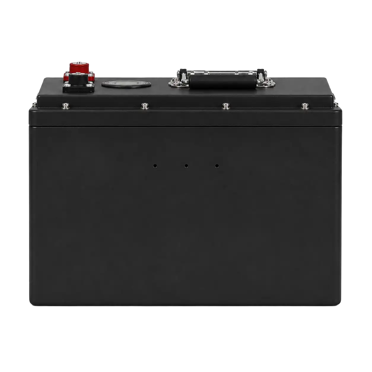
Check enclosure space, mounting, terminals, connectors, cable routing and service access.
Share application, environment, quantity, compliance and integration requirements with engineering.
Products
Compare the available models below, then open a product page for detailed specifications and project matching.
Battery packs for robotic equipment, organized for comparison by voltage, capacity, pack format and integration needs.
Guidance on product selection, application fit and project requirements for this category.
Use the DC bus and motor-controller requirements as the reference. List the input ranges of motors, actuators, computers, sensors and DC/DC converters, then confirm that the battery’s full voltage window from full charge to cut-off remains within the system limits.

Use watt-hours whenever possible. Add the average power of drives, actuators, computing and auxiliary equipment, then multiply by operating time to estimate Wh. Add margin for permitted discharge range, conversion losses and task variation.
Measure the worst operating condition rather than no-load behavior. Record maximum current, duration and repetition during simultaneous startup, acceleration, lifting or braking, then confirm that the BMS, connectors, wiring and fuse can support it.
Only when the control system must read or control battery data. List the required signals, such as state of charge, voltage, current, temperature, alarms, permitted charge/discharge current and contactor status, then provide protocol, baud rate, node address and message table.
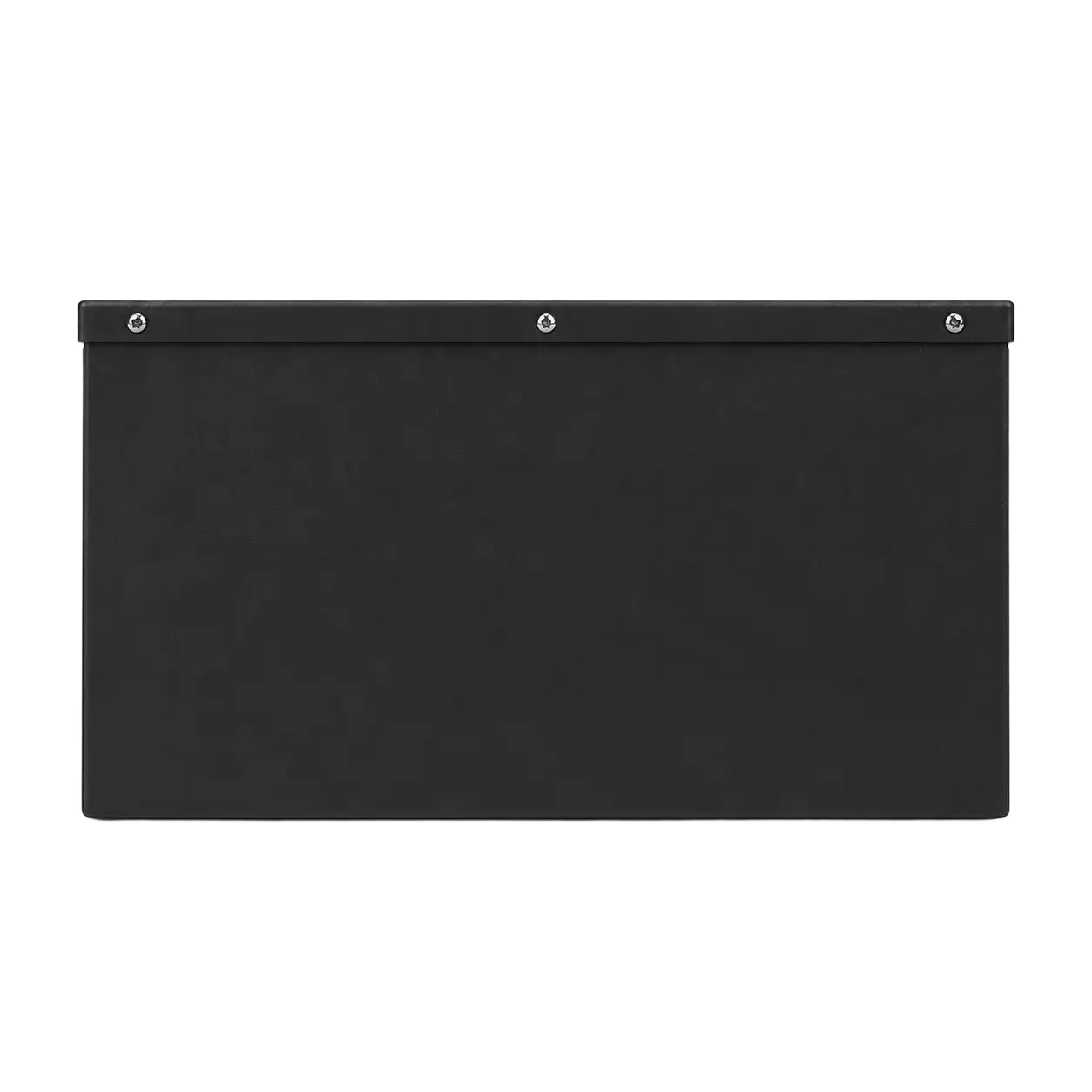
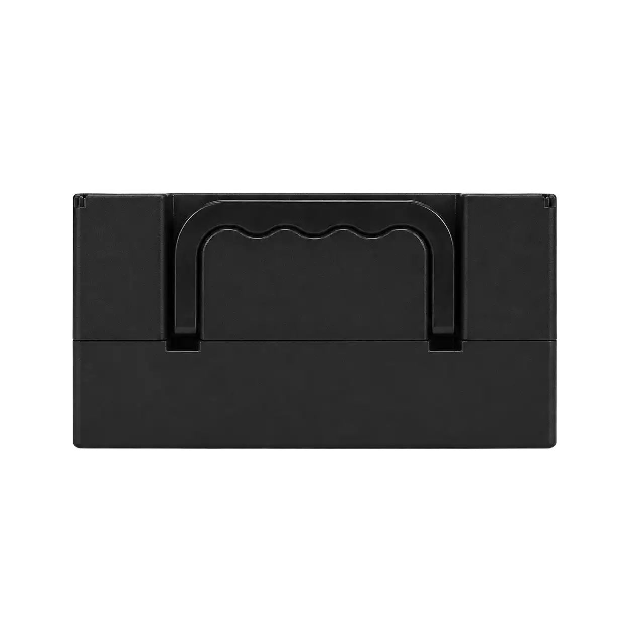
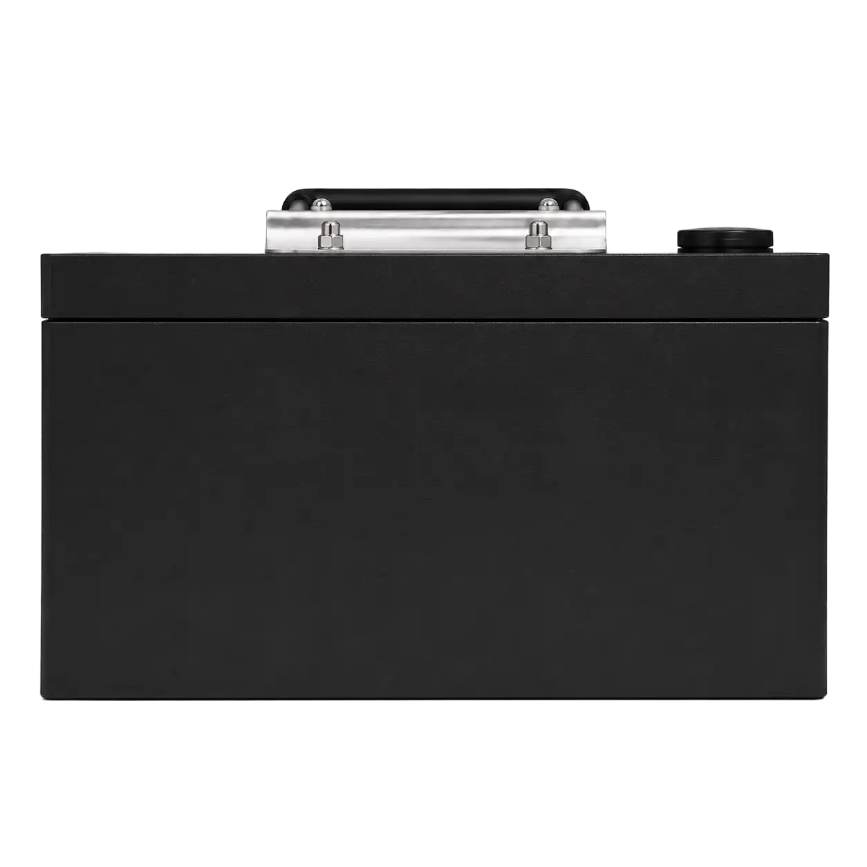
Freeze the installation envelope and interfaces first. Provide a 3D space claim or dimensioned drawing, mounting points, center-of-gravity and weight limits, connectors, cable routes, cooling, service direction, enclosure rating and shock or vibration conditions.
Contact Us