Charge a LiFePO4 trolling motor battery with a charger that matches its voltage, charging profile and current limit. For everyday AC charging, that can be a permanently installed onboard charger or a suitable portable unit. Check the battery temperature and the charger’s settings, then follow the equipment instructions for starting and ending the charge.
A 24V or 36V setup needs a closer look: one complete battery pack and several 12V batteries connected in series may need different charging arrangements. Below, we explain routine charging, charging time, multi-bank charger labels, and options for charging from the engine or solar panels.
How to charge an installed LiFePO4 system
These steps are for normal use of a correctly installed system. Installing a charger, changing cables or altering a battery bank is a separate job for a qualified marine electrical technician.
- Identify the battery setup. Check the battery model, chemistry and voltage. For several batteries, confirm how they are connected and which charger output serves each battery.
- Check condition and temperature. Do not charge a damaged, unusually hot or water-damaged battery. Check that its temperature is within the manufacturer’s charging range; warm air does not guarantee a cold battery has warmed up.
- Check the charger profile. Use a setting compatible with the exact LiFePO4 battery. Do not assume a lead-acid setting is suitable or enable equalization, desulfation or repair modes.
- Prepare and start charging. Turn the trolling motor off and follow the charger’s connection and power-up sequence. Check plugs and cables for damage. With a portable unit, follow its mounting, ventilation and weather-exposure limits.
- Check that charging has started normally. Read the display or status lights using that charger’s manual. If it reports a fault or repeatedly stops and restarts, stop and investigate rather than forcing a reset.
- Finish according to the equipment instructions. Use the charger’s completion indication, not a single voltage reading. Follow its shutdown sequence before moving a portable charger or changing connections.
If the system is unfamiliar or you cannot identify the settings, check the manuals or ask the installer before charging. Do not work on energized wiring.
Onboard or portable: which AC charger fits?
An onboard charger stays mounted in the boat, which makes regular charging convenient. A portable charger can be useful when charging ashore or when the boat has no permanent charger. Neither label proves LiFePO4 compatibility: check the actual model, output voltage, current and charging profile.
Shore power is the AC supply, not a separate battery-charging method. It feeds the charger, which converts and controls the power sent to the battery. A boat’s shore inlet and AC protection must suit the installation; a portable charger’s instructions may specify a different way to connect to an AC outlet.
Some onboard chargers also charge the starting battery. Set each output for the battery connected to it. Do not change the starting battery’s profile just because the trolling battery has been replaced with lithium. For the charging stages and settings behind these checks, see our LiFePO4 charger compatibility guide.
Read 12V, 24V, 36V and multi-bank labels correctly
On a boat, a battery bank means a battery or group working together. On a charger, “bank” often means one charging output. That difference matters when reading the label.
| Your battery setup | What to check on the charger | Mistake to avoid |
|---|---|---|
| A single 12V-class LiFePO4 battery | A compatible 12V-class lithium output, with the correct voltage profile and current limit | Assuming every “12V” setting is suitable |
| A complete 24V or 36V battery pack | An output designed for that pack’s voltage and charging requirements | Using one 12V output across the higher-voltage pack |
| Approved 12V batteries connected in series | An approved whole-bank charger, or isolated outputs for individual batteries where both manufacturers allow it | Assuming output count alone confirms voltage or connection compatibility |
As a hypothetical example, a charger has three separate outputs rated at 10A each, for 30A total. That does not mean it has a single 36V/30A output. Check the voltage, current and approved connections for each output; this example does not approve any charger for a particular Hysincere battery.
Never assume that a battery supports series connection just because the voltages add up. Likewise, do not combine charger outputs or change series links unless the battery and charger instructions explicitly permit the arrangement.
How long will charging take?
Start with the amount of charge you need to replace, not the battery’s full capacity every time.
Ideal charging time (hours) ≈ capacity to replace (Ah) ÷ battery-side charging current (A)
As a calculation example, a 100Ah battery going from an estimated 20% to 100% needs about 80Ah replaced. With no simultaneous load and a constant battery-side charging current:
| Battery-side current | Ideal time to replace 80Ah |
|---|---|
| 10A | About 8 hours |
| 20A | About 4 hours |
This is a mathematical estimate, not a Hysincere test result or a recommended current for a specific model. Actual charging takes account of current taper near completion, charger limits, battery condition, temperature, SOC estimation and any equipment drawing power. Allow time beyond the ideal figure when planning your next trip.
For a multi-output charger, use the current reaching each battery—not the total current printed on the charger. If batteries charge at the same time, do not add their charging times together as though they were charged one after another. Battery sizing and on-water runtime are covered separately in the trolling motor battery size and runtime guide.
Can the engine charge the trolling battery?
Yes, with a compatible charging system. A suitable DC-DC charger can regulate the charge sent from the engine or starting-battery side to the trolling bank. This is useful for topping up during a run, but a short engine trip may not replace a full day’s trolling energy.
The charger needs the right input and output voltage ranges, LiFePO4 profile and current limits. Engine-running detection or another suitable control should stop it drawing down the starting battery after the engine stops. “DC-DC” does not automatically mean galvanically isolated; grounding and isolation requirements depend on the device and boat.
Do not size the DC-DC charger from the alternator’s headline rating alone. Engine loads, starting-battery recharge, temperature and low-speed operation leave less power available. Confirm current limits and engine-off control against the engine, charger and battery manuals. Do not directly join the lithium trolling bank to the starting battery as an improvised charging method.
Can solar panels recharge the battery?
Yes, through a compatible solar charge controller, often an MPPT controller. The controller must support the battery voltage and LiFePO4 settings, while staying within its solar-input voltage and current limits. Solar panels should not connect directly to the battery.
Whether solar provides a small top-up or a substantial recharge depends on panel area, shading, season and time in the sun. Compare expected daily energy yield with the energy used on the water; panel wattage alone does not establish a full recharge time.
Solar may start charging while the boat is unattended. Confirm how charging is stopped when the battery is too cold or too hot, and use a suitable battery-temperature measurement or control signal. Do not rely on the air temperature at the helm.
Check combined charging current and battery roles
If AC, DC-DC and solar charging can operate together, add their maximum battery-side currents and compare the total with the battery and installation limits. Do not rely on the motor or other loads to keep the net current down: those loads can stop while the chargers keep running.
The installer should also check that the sources use compatible voltage targets and respond properly to a BMS charge stop. Repeated BMS interruptions are a reason to investigate, not a normal way to finish every charge.
The trolling bank powers the electric motor; the starting battery cranks the engine; a separate house battery, if fitted, supplies equipment such as electronics and lighting. Keep their duties clear. A deep-cycle rating or a high peak-discharge number alone does not establish engine-starting suitability.
Charging specifications for the LF12100-HL-TM
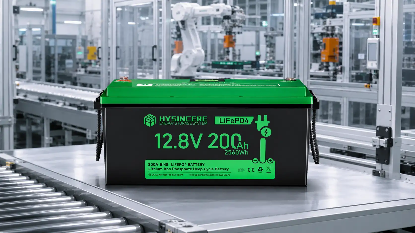
The Hysincere LF12100-HL-TM is a 12.8V, 100Ah LiFePO4 battery with 1280Wh nominal energy. Its published charging limits help you screen a charger:
- 12.8V nominal voltage: identifies its 12V-class battery platform; it is not the charging-voltage setting.
- 14.6V maximum charge voltage: a limit, not an instruction to hold the battery at that voltage indefinitely.
- 100A maximum charge current: an upper limit, not a recommendation to use a 100A charger for daily charging.
- 0–55°C charging range: assess the battery temperature as specified by the manufacturer, rather than just the surrounding air.
Choose the actual profile and everyday current using the current model instructions and the recharge time you need. Ask us to check the charger model if those settings are unclear. This article uses the LF12100-HL-TM as a trolling motor battery; it does not claim engine-starting capability or approve a particular charger combination.
If charging will not start or stops early
Check the charger’s fault indication, battery temperature, selected profile and battery power state. A charger may not detect a battery whose BMS has turned its output off. Use only the documented recovery method for that battery and charger; do not bypass the BMS or repeatedly force a wake-up.
If it says “full” much earlier than expected, compare the starting charge level, current and any battery warnings. A completion light is useful, but an unexplained change still deserves investigation. Stop for damaged cables, water intrusion, abnormal heat or recurring protection events.
When contacting support, start with the battery model, charger model, battery arrangement and a photo of the fault indication. For a new boat project, the trolling motor battery application guide covers the wider selection requirements.
Not sure whether your charger is compatible?
Send us the battery model, charger model and your 12V, 24V or 36V arrangement. We can help check battery-side compatibility before you choose equipment.
Trolling Motor Battery Charging FAQ
Practical answers about existing chargers, recharge time and charging problems.
Can I keep my old lead-acid charger after switching to LiFePO4?
Only if its exact model and settings are approved for the new battery. A suitable lithium mode may be available, but the voltage profile and current limit still need checking. Do not use lead-acid equalization, desulfation or repair modes on the LiFePO4 battery.
How long does a 100Ah trolling motor battery take to charge?
It depends on how much charge is missing and the current reaching the battery. Replacing 80Ah at a constant 10A gives an ideal 8 hours, or 4 hours at 20A. These are calculation examples, not recommended settings or measured results; taper, temperature, loads and charger limits affect actual time.
Does a three-bank charger provide a 36V output?
Not necessarily. It may have three separate 12V outputs rather than one 36V output. Check each output's voltage, current and isolation, plus the approved battery arrangement. Do not combine outputs unless the charger instructions explicitly allow it.
Can I leave the charger connected after the battery is full?
Only where both the battery and charger instructions permit it. Automatic charge completion does not, by itself, approve indefinite connection or storage charging. Follow the specified storage settings and temperature limits, especially if solar or another source can restart charging while the boat is unattended.
Why will the charger not detect my battery?
Check the fault indication, battery switch, temperature and selected profile. If the BMS has disconnected the output, the charger may not detect the battery. Use the documented recovery procedure for that combination; do not bypass protection or force repeated restarts.
Can the alternator and solar panels charge the battery together?
They can in a properly designed system with a compatible DC-DC charger and solar controller. Check the combined maximum battery-side current, voltage settings and response to a BMS charge stop. Protect the starting battery from engine-off discharge, and do not connect solar panels directly to the battery.
Follow the current battery, charger and boat instructions. Installation, wiring changes and multi-source charging need a qualified marine electrical technician; isolate every power source before changing connections. Stop charging if the battery is damaged, unusually hot or repeatedly enters protection.