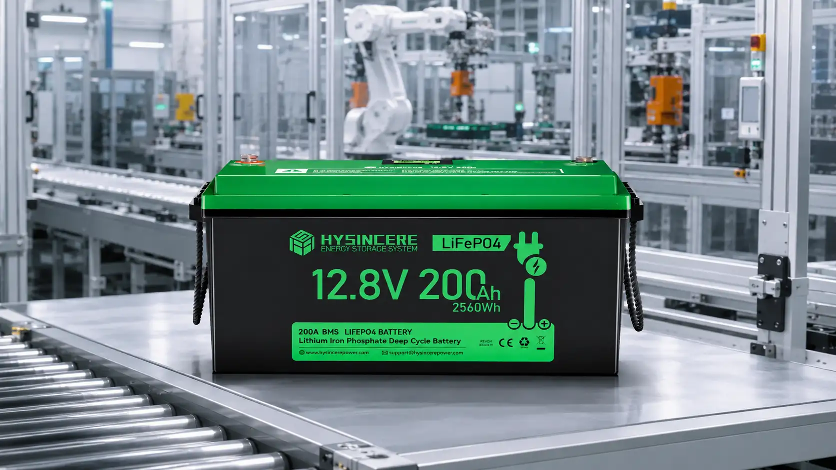
A 12.8V LiFePO4 battery can operate many devices sold for a nominal 12V lead-acid system, but the two labels do not prove compatibility. The useful question is not “Is 12.8V too high?” It is whether the charger, load, inverter, controller, alarm thresholds, and battery management system share a safe operating window.
This distinction matters in RV house banks, boats, solar systems, mobility equipment, and industrial DC installations. The battery may fit the tray and power the load on day one, yet an overlooked voltage setting can still cause incomplete charging, premature low-voltage alarms, or an abrupt BMS shutdown in service.
The practical answer: compatible in many systems, interchangeable in fewer
A conventional 12V lead-acid battery is built from six cells and is described by a 12.0V nominal rating. A typical 12V-class LiFePO4 battery uses four cells in series and is described as 12.8V nominal. Neither number is the voltage the equipment sees at every moment. Both chemistries move through a wider voltage range while charging and discharging.
That is why a 12.8V battery is not automatically “too high” for 12V equipment. Many nominal-12V devices were designed to tolerate the higher voltage present while a lead-acid battery is being charged. However, this does not make every device suitable. Sensitive electronics, fixed-voltage chargers, old battery gauges, and equipment with narrow alarm thresholds need individual review.
If you are at the beginning of a conversion, use the broader lead-acid to LiFePO4 system checklist to identify the full set of mechanical, charging, current, and environmental questions. This article stays focused on voltage behavior.
Why a nominal voltage is useful—but not enough
Nominal voltage is a convenient classification. It allows designers to group batteries and equipment into 12V, 24V, 36V, or 48V families. It is not a charger setting, a low-voltage cutoff, or a promise that two products can be exchanged without adjustment.
For a proper comparison, collect four voltage values from the battery specification and four from the equipment:
- Battery: nominal voltage, recommended charge range, BMS high-voltage protection behavior, and BMS low-voltage protection behavior;
- Equipment: permitted input range, low-voltage warning, low-voltage shutdown, and highest voltage tolerated during charging.
The numbers must be reviewed as a set. A charger can be below the BMS protection limit and still be a poor long-term match. Likewise, a load can run normally at mid-state of charge but shut down early because its lead-acid-oriented threshold is set too high for the intended lithium operating window.
12V lead-acid and 12.8V LiFePO4 do not behave the same way
| Point of comparison | 12V lead-acid system | 12.8V LiFePO4 system | Why the difference matters |
|---|---|---|---|
| Nominal label | Normally 12.0V for a six-cell battery | Normally 12.8V for a four-cell battery | The label identifies the system family; it is not the operating limit |
| Discharge curve | Voltage generally falls more visibly as state of charge and load change | Voltage remains comparatively flat through much of the discharge | A lead-acid voltage gauge may show an inaccurate lithium state of charge |
| Voltage sag under load | Can be more pronounced, especially at high current or with an aged battery | Often lower until the pack approaches a protection threshold | Equipment may appear to run more steadily, but shutdown can be less gradual |
| Charge holding | Standby systems commonly use a continuous float strategy | Continuous lead-acid-style float may be unnecessary or unsuitable, depending on the model | The charging profile must be checked, not assumed from voltage alone |
| Temperature compensation | Frequently used by lead-acid chargers | Must follow the battery maker’s lithium specification; lead-acid compensation should not be carried over automatically | Cold conditions can push a lead-acid profile in the wrong direction for lithium |
| Low-voltage endpoint | Equipment often warns as voltage gradually declines | The BMS can disconnect the pack when a cell or pack limit is reached | Alarm and shutdown coordination are important for a controlled stop |
The table describes common behavior, not universal setpoints. Always use the selected battery, charger, and equipment documentation for final values.
Six voltage-related checks before connecting a LiFePO4 battery
- Write down the equipment input range.
Check the inverter, controller, DC loads, pumps, electronics, relays, and any 12V accessory circuits. “Automotive 12V” or “nominal 12V” is not as useful as a stated minimum and maximum input voltage. - Review every charging source.
A system may have an AC charger, alternator, solar controller, converter/charger, and inverter/charger. One compatible device does not make the other sources compatible. The dedicated guide on using lead-acid charging equipment with LiFePO4 explains what to check in each source. - Coordinate low-voltage alarms and shutdowns.
Ideally, the system should warn the operator and reduce or disconnect noncritical loads before the battery reaches a hard BMS cutoff. If the BMS is the first and only protection to act, the result can be an abrupt loss of power. - Confirm the BMS current rating as well as voltage.
Correct voltage does not compensate for an undersized BMS. Compare maximum continuous load, startup surge, surge duration, charge current, and possible regenerative current with the battery limits. - Replace or recalibrate the state-of-charge display if necessary.
A gauge designed around lead-acid voltage can be misleading on a flatter LiFePO4 discharge curve. Check whether the display can use a lithium profile, shunt-based measurement, Bluetooth data, CAN, or RS485 as required by the project. - Test the complete operating window.
Verify cold start, maximum load, charger transition, low-state-of-charge behavior, recovery after protection, and normal shutdown. A bench reading at no load is not a substitute for a system test.
Example: the voltage label says little about inverter current
Consider a nominal-12V system operating a 1,000W AC load through an inverter. If 90% inverter efficiency is used only as an illustrative planning assumption, the approximate battery current at 12.8V is:
The calculation immediately raises questions that the words “12V compatible” cannot answer:
- Can the battery and BMS deliver about 87A continuously at the target temperature?
- Does the load have a startup surge above 1,000W?
- Will the inverter’s low-voltage setting provide a useful warning before the BMS disconnects?
- Are the cable, fuse, disconnect, terminals, and busbar designed for the current?
The same discipline applies to energy. Compare watt-hours and the real duty cycle rather than assuming that equal amp-hour labels produce equal runtime. Hysincere’s 12V 100Ah battery selection guide covers load and runtime sizing in more detail.
The answer changes with the application
RV and marine house batteries
Many house loads accept the practical voltage range of a 12.8V LiFePO4 bank, but the conversion still needs a review of the converter/charger, alternator path, solar controller, inverter, battery monitor, and low-temperature charging. A house battery must also be kept separate from engine-starting duty unless the selected battery is expressly designed and approved for both.
Solar and stationary backup
Inverter/chargers and solar controllers often provide adjustable lithium settings, but the selected profile must match the battery data. Also verify the inverter’s low-voltage shutdown and restart values. In a backup system, unexpected BMS disconnection may affect alarms, communications, and automatic recovery after grid power returns.
Motors, pumps, and mobility equipment
These applications may look straightforward because the controller is already described as 12V, 24V, or 36V. In practice, acceleration, locked-rotor current, regenerative braking, and controller undervoltage/overvoltage thresholds can dominate the design. Use the real controller and motor data, not only the old battery label.
Critical UPS and safety-related equipment
A small SLA battery should not be replaced in critical equipment merely because a LiFePO4 pack has similar dimensions and nominal voltage. Charger behavior, high-rate discharge, BMS cutoff, runtime estimation, certification, warranty, and fault recovery all need equipment-level approval. The dedicated 12V 7Ah SLA-to-LiFePO4 UPS guide explains this boundary.
Prepare this information before requesting a battery recommendation
- Existing battery chemistry, model, voltage, capacity, dimensions, and terminal layout;
- Equipment minimum/maximum input voltage and low-voltage warning/shutdown settings;
- Every charger’s brand, model, output range, current, and enabled charge modes;
- Average load, highest continuous load, startup surge, and required runtime;
- Minimum and maximum battery temperature during charging and discharging;
- Whether the system includes an alternator, solar controller, inverter, motor controller, or regenerative charging;
- Monitoring method and any CAN, RS485, Bluetooth, or display requirements;
- Series/parallel plan, target market, documentation, certification, and annual project volume.
For current product directions, review Hysincere’s LiFePO4 lead-acid replacement battery range and 12V battery platform. The product datasheet for the final model remains the controlling technical reference.
Check the operating window before treating the conversion as a battery swap
Send Hysincere the existing battery model, equipment voltage limits, charging sources, load current, temperature range, and required runtime. The result should be a battery and system proposal that can be verified against real operating conditions—not a decision based only on the word “12V.”
12V lead-acid and 12.8V LiFePO4 FAQ
Is a 12.8V LiFePO4 battery too high for 12V equipment?
Not necessarily. Many 12V devices already experience voltage above 12V while a lead-acid battery is charging. Compatibility still depends on the device’s permitted input range, the lithium battery’s operating limits, charger settings, and alarm thresholds. Confirm the real ranges rather than deciding from nominal labels.
Why does a 12V lithium battery say 12.8V?
A common LiFePO4 design uses four cells in series, each with a nominal value around 3.2V, producing a 12.8V nominal pack. A 12V lead-acid battery commonly uses six 2V nominal cells. Both are 12V-class batteries, but their voltage curves and charging requirements differ.
Can I keep the old lead-acid battery gauge?
It may continue to display voltage, but its state-of-charge estimate can be inaccurate because LiFePO4 has a flatter discharge curve. For a more useful reading, consider a lithium-configurable shunt monitor, valid BMS data, or the communication method supported by the selected battery.
Should the inverter low-voltage cutoff be changed?
Possibly. The correct setting depends on the inverter, load behavior, cable voltage drop, battery specification, and desired reserve. The aim is to provide a controlled warning or shutdown before a hard BMS disconnect without ending normal operation too early.
Can I connect three 12.8V batteries to replace a 36V lead-acid bank?
Only if the exact battery model is approved for series use and the full bank design follows the manufacturer’s limits. Use matched batteries, align their state of charge, and confirm charger voltage, BMS switching capability, cabling, and protection. A native 38.4V pack may be a cleaner option for some projects.
This article supports preliminary system evaluation. Final settings and installation must follow the documentation of the selected battery, charger, inverter, controller, vehicle, vessel, or equipment manufacturer and applicable local requirements.