A LiFePO4 battery can be a practical choice for a mobile robot that works repeated shifts and has enough space for the required pack. Start with the robot’s operating voltage, measured energy use, peak current and charging schedule. Then check whether the battery management system can work with the robot controller and charger.
This guide covers automated guided vehicles (AGVs), autonomous mobile robots (AMRs), factory transport robots and wheeled service robots used for delivery, cleaning or inspection. These categories can overlap: a service robot may also use an autonomous mobile platform. Battery requirements depend on payload, travel routes and onboard equipment. A pack that works in one platform may need different electrical connections, protection settings or mechanical packaging in another.
Where LiFePO4 fits in a robot battery design
LiFePO4, also called LFP, is a lithium-ion chemistry. Its thermal stability and potential for long cycle life make it worth evaluating for equipment that charges and discharges frequently. The tradeoff is energy density: compared with many nickel-based lithium-ion designs, it can require more space or weight for the same stored energy.
For a wheeled robot, the decision therefore starts with the available battery bay and duty cycle. For a compact robot with a tight weight limit, compare complete pack designs before choosing the chemistry. The enclosure, connectors and protection hardware also take up space.
Ask for cycle-life test conditions when comparing suppliers: temperature, charging rate, discharge rate, depth of discharge and the remaining capacity used to define end of life. A cycle count without those conditions tells you little about performance on your route.
Different jobs create different battery demands
A warehouse or factory transport robot may spend much of its shift moving loads, turning and waiting at transfer points. Measure a representative loaded route, including any lifting mechanism. A battery selected from empty-vehicle consumption can underestimate the energy needed in service.
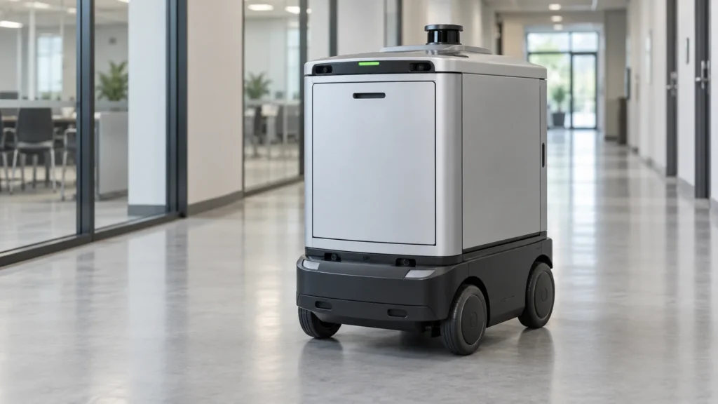
A wheeled delivery robot may travel between reception areas, production stations or other indoor destinations. Its load profile includes frequent stops as well as navigation, computing and standby power. Check thresholds, ramps and time spent waiting for the next job when estimating runtime.
A cleaning robot adds brushes, pumps or suction to its traction load. An inspection robot may carry cameras, lighting or other instruments that remain active while it is stationary. These are different energy budgets even when the chassis and nominal voltage look similar.
Treat these as applications to evaluate, rather than proof that one battery fits all of them. The useful comparison is the complete duty cycle, available installation space and charging schedule of each robot.
What about LiFePO4 for humanoid robots?
LiFePO4 can be considered for a humanoid robot if a complete pack meets the platform’s mass, space, power and runtime requirements. Choosing it requires a different assessment from placing a battery inside a wheeled base.
For a walking platform, ask the robot designer for battery mass and center-of-mass limits, as well as current measurements during standing, walking, lifting and transitions between movements. A pack with sufficient watt-hours may still exceed the weight allowance or fail to supply repeated current peaks.
Compare complete candidate packs and validate the chosen design in the robot. A product described as a “robot battery” does not by itself establish compatibility with a particular humanoid platform. For a humanoid project, supply the movement profile and mechanical limits before requesting a battery recommendation.
Match the full voltage range
A “24V robot” label is only a starting point. Check the operating range of the motor controllers, onboard computer, sensors, DC-DC converters and charger.
An eight-cell series LiFePO4 pack has a nominal voltage of about 25.6V when each cell is rated at 3.2V. Its voltage changes during use and charging. The robot must tolerate the pack’s approved upper voltage and keep operating above its lower limit under load. Set the charging voltage from the specific battery specification.
Also establish what happens as the battery approaches empty. The robot should have enough usable energy to return to its dock or stop in a suitable location before a protective battery shutdown interrupts power.
Calculate capacity from the actual duty cycle
Use watt-hours (Wh) to estimate the energy needed between charging opportunities. Include driving, turning, lifting, computing, sensing and waiting. A cleaning robot also needs an allowance for brushes, pumps or suction motors.
Measure consumption at the battery terminals over a representative route where possible. Multiplying a motor’s rated power by the entire shift can substantially misrepresent actual use.
Illustrative sizing example—not a product specification: suppose the robot draws an average of 250W from the battery and needs four hours between charges.
- Energy required: 250W × 4h = 1,000Wh.
- Assume an operating window that uses 80% of the battery’s available capacity.
- Assume the robot must still meet that runtime when the battery retains 80% of its original capacity.
- Required new-pack nominal energy: 1,000Wh ÷ (0.80 × 0.80) ≈ 1,563Wh.
- At a nominal 25.6V: 1,563Wh ÷ 25.6V ≈ 61Ah.
Under these assumptions, a 25.6V 60Ah pack is slightly below the calculated requirement. Assess the next suitable capacity against its measured performance, size and current limits. Cold conditions, longer routes and payload changes may require further allowance.
Because the assumed 250W is measured at the battery, it already includes downstream conversion losses. If your starting point is mechanical output or power measured after a converter, account for the intervening losses separately. The two 80% factors above are design assumptions, not universal LFP operating limits.
Check current separately from capacity
Amp-hours describe capacity; they do not establish how much current the pack can deliver. A battery may store enough energy for the shift and still disconnect during acceleration or lifting.
Record the continuous current, the highest current peaks, how long each peak lasts and how frequently it repeats. Evaluate these at the lowest intended operating voltage and relevant temperatures.
For example, a hypothetical 2,000W electrical demand at a 22V battery bus requires about 91A. That is a different requirement from the average load used for runtime sizing. Check the cells, BMS, conductors, fuses and connectors as a complete current path.
Some drive systems also return energy to the battery while braking. Where regeneration is used, the controller must respect the battery’s available charge-current limit, including when the pack is nearly full.
Plan charging around the robot’s work
A robot that charges overnight needs a different energy plan from one that returns to a dock between jobs. For opportunity charging—short charging periods during normal operation—calculate both the energy used between visits and the energy actually recovered at the dock.
For illustration, 800W of net charging power maintained into the battery for 15 minutes supplies 200Wh of electrical energy. The energy available for later work will be lower after storage and discharge losses. Docking delays, onboard loads and charging-current taper can reduce recovery further. Use logged charging data to validate the schedule.
Match the charging profile, maximum voltage and current to the exact pack. Check docking contact ratings, wake-up behavior and how charging stops when the BMS withdraws permission. The LiFePO4 charging compatibility guide explains the underlying charger checks.
Cold environments need particular attention. Charging and discharging have different temperature limits, and the allowed charging temperature varies by product. Follow the selected battery’s instructions and confirm that any heating system brings the cells into their permitted charging range.
Make the BMS useful to the robot controller
The battery management system monitors and protects the pack. The robot also needs usable information about remaining charge, temperature, current limits and faults so it can manage its work before protection intervenes.
Ask for a communication specification early. A CAN or RS485 interface alone does not establish compatibility. Confirm message definitions, units, update rates, wiring, termination where required, and the response to lost communication. Define how the robot reduces load, returns to charge or stops when battery conditions change.
Do not rely only on terminal voltage to schedule charging. Use a state-of-charge estimate validated for the chosen cells and operating profile. Battery gauges can combine current, temperature and battery models to estimate remaining charge.
For OEM integration, prepare the electrical requirements and communication details together with the mechanical drawing. These are useful inputs when discussing custom lithium battery solutions.
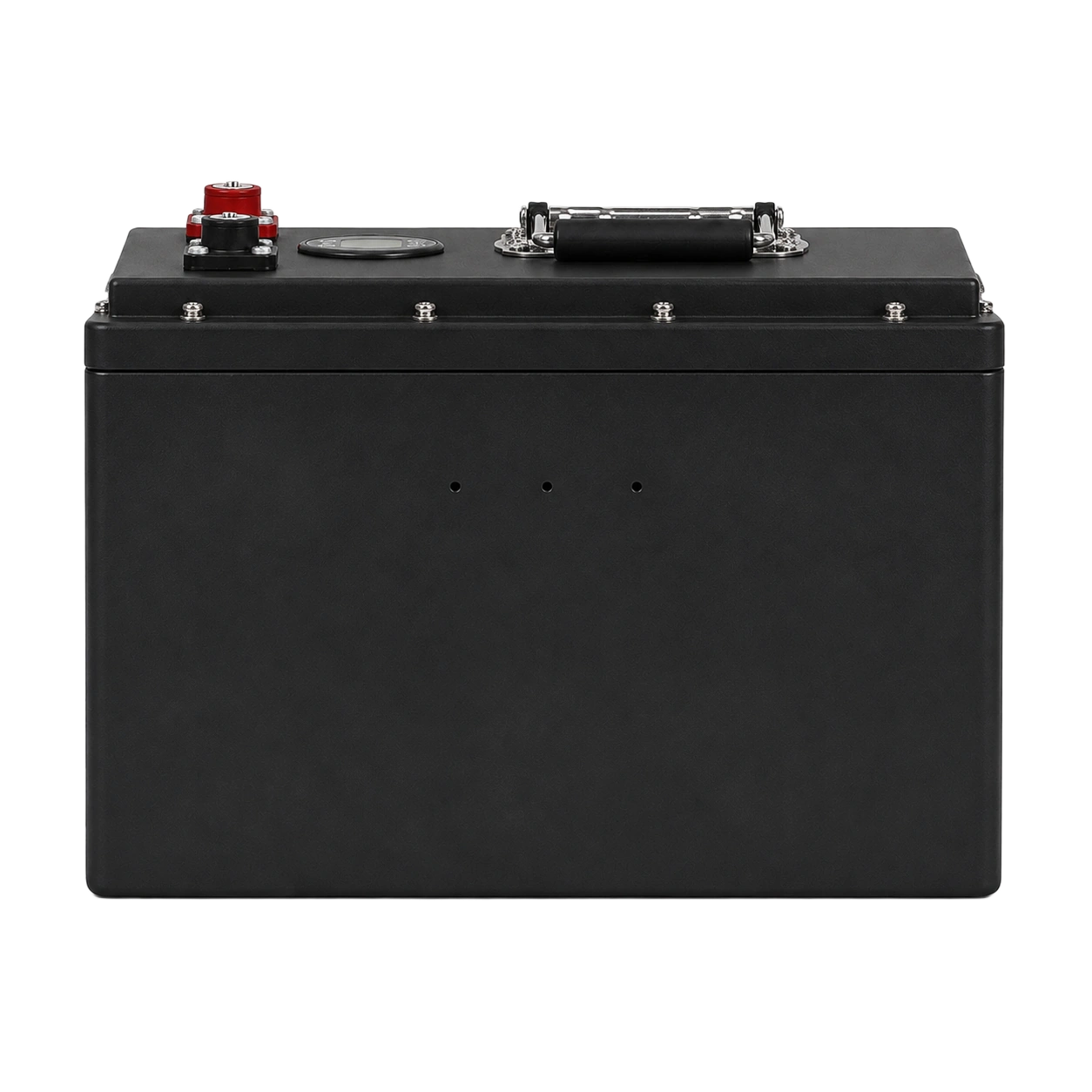
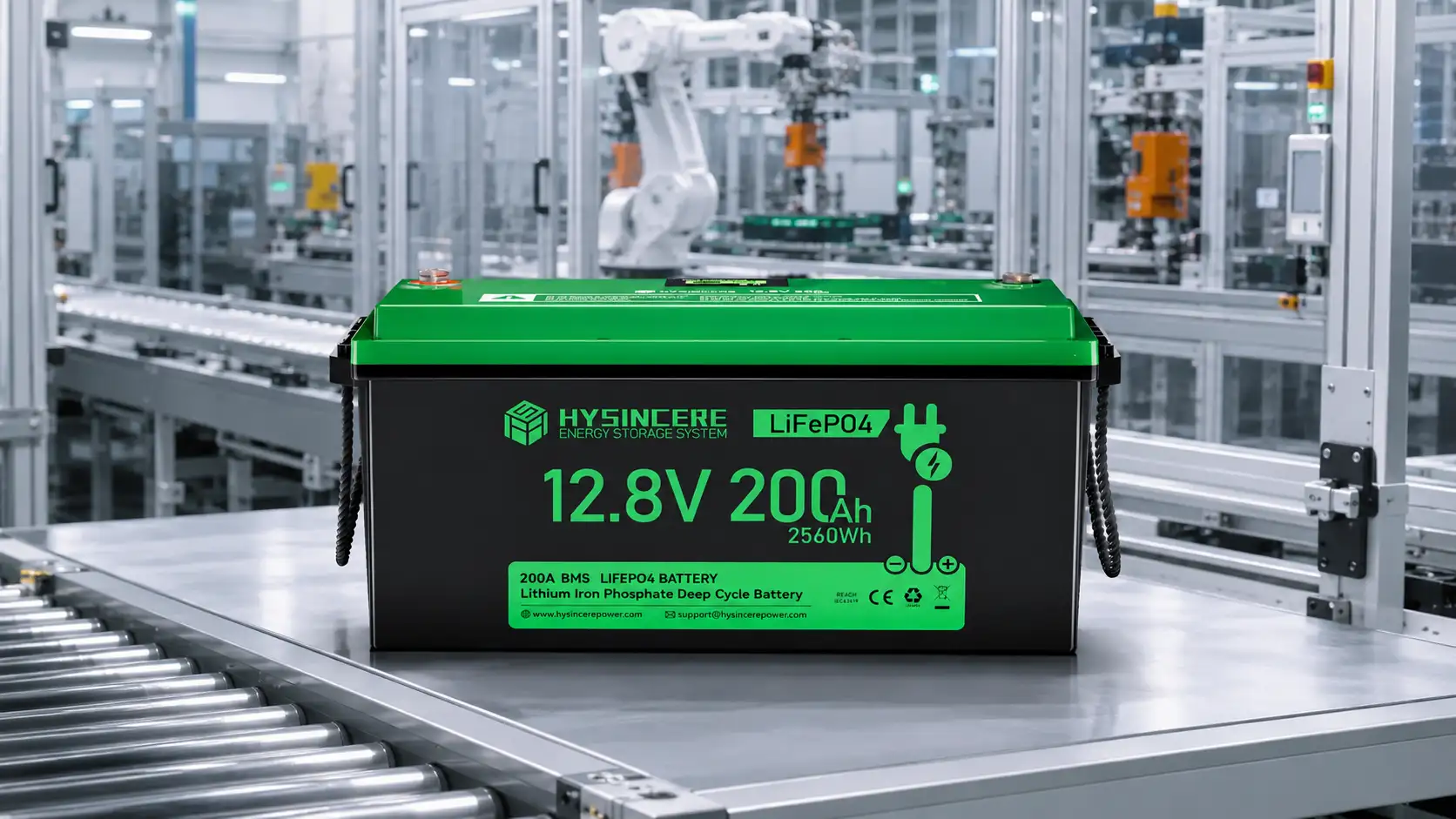
For a concrete product reference, Hysincere’s LiFePO4 8S1P 100Ah robot battery pack is listed at 25.6V and 2,560Wh, with CAN and RS232 communication. Its listed dimensions are 172 × 315 × 315mm and its weight is 21.35kg. These specifications make the energy, interface and packaging tradeoffs tangible; they do not establish suitability for a particular robot. Compare all electrical limits and the communication protocol before treating it as a candidate.
Validate the pack in the actual robot
A bench test confirms only part of the design. Run the intended route with realistic payloads, starts, turns, stops and charging visits. Include the lowest planned state of charge and the expected temperature range.
During validation, record pack voltage, current peaks, temperature, energy consumption, reported state of charge and protection events. Check whether the robot completes its work and reaches the dock with the planned reserve. Repeat docking cycles to assess contacts, alignment and charging interruptions.
Before requesting a sample, provide the supplier with:
- Operating voltage range, measured duty cycle and required runtime.
- Continuous current, peak current with duration, and regeneration requirements.
- Available charging time, charger details and docking interface.
- Battery-bay dimensions, weight limit, mounting and connector arrangement.
- Working temperatures, exposure to water or dust, and vibration conditions.
- Communication protocol, fault responses and documents required by the project.
This gives both teams a clear basis for comparing candidate packs and agreeing on sample acceptance criteria.
Discuss your robot battery requirements
Preparing a mobile or service robot project? Send Hysincere the robot’s intended job, voltage range, load measurements, charging schedule and battery-bay drawing through the project inquiry page. Include the controller protocol so electrical, mechanical and communication requirements can be reviewed together.
Frequently asked questions
Does every robot battery need CAN communication?
The interface should follow the robot’s control requirements. Some platforms use simpler status signals; others need detailed battery data and current limits. Where CAN is used, both sides must support the same message protocol.
Can a robot’s lead-acid battery be replaced with LiFePO4?
It may be possible after checking voltage range, charger compatibility, current, mounting, communications and protection behavior. Similar nominal voltage or enclosure dimensions do not establish a direct replacement.
Is LiFePO4 suitable for every robot?
Suitability depends on energy demand, space, weight, current and charging conditions. LFP is worth evaluating for wheeled robots with frequent use, but compact or weight-sensitive platforms need a comparison of complete pack options.
Does a larger Ah rating mean more power?
A larger Ah rating means more stored charge at the stated voltage. Available power also depends on the voltage and permitted discharge current. Check continuous and pulse ratings separately.
The sizing examples use stated assumptions. Confirm final electrical, charging and mechanical requirements against the selected pack and robot specifications.