
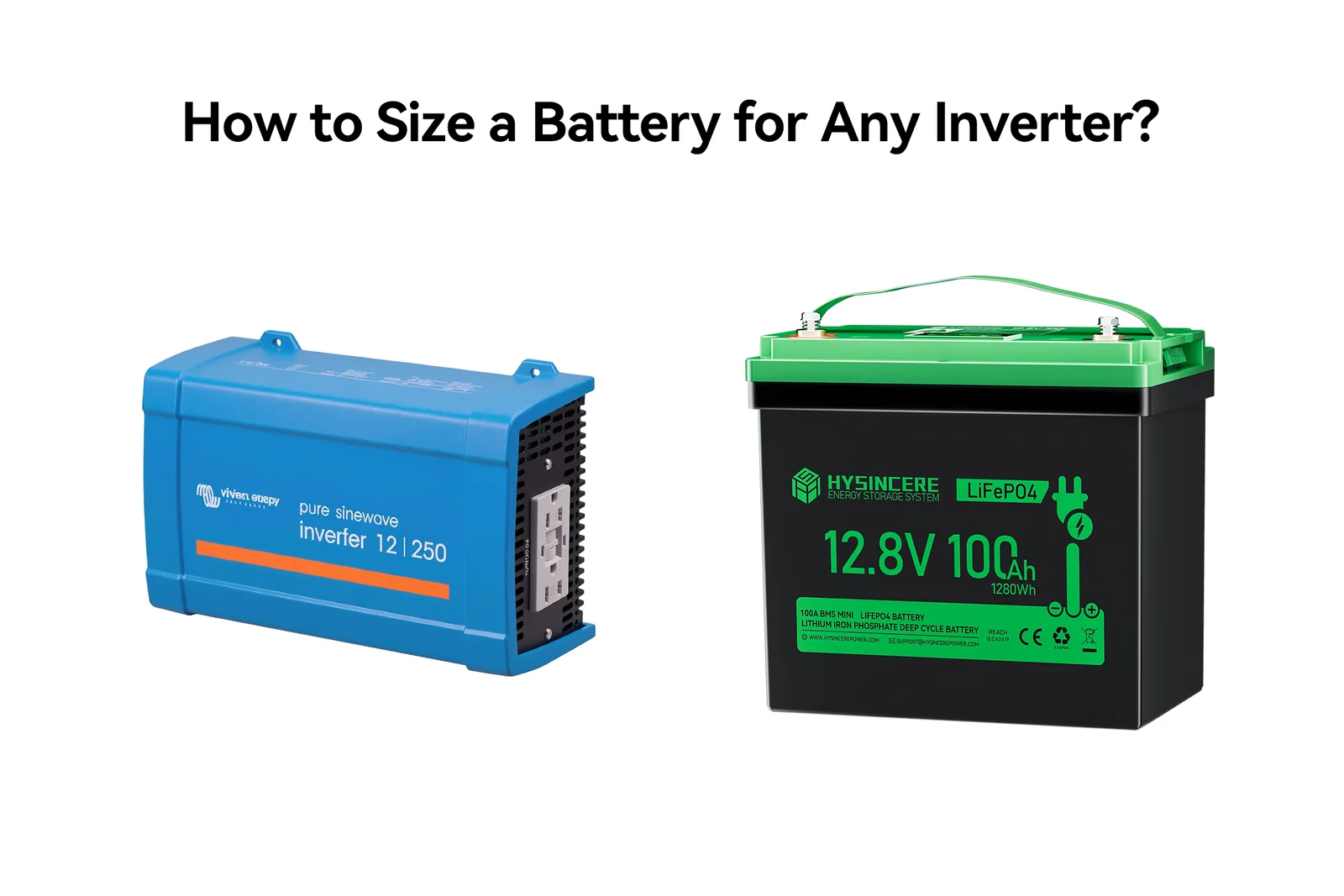
If you are replacing an AGM, gel or flooded lead-acid bank with LiFePO4, matching the Ah rating of the old battery is not enough.
Before choosing the replacement, check whether the battery can supply the inverter’s continuous and surge current without tripping the BMS, and whether it stores enough usable energy for the required runtime.
LiFePO4 often provides more usable energy than a lead-acid battery with the same Ah rating, but the inverter, charger, cabling and protection still have to be compatible.
The examples below cover 1000W, 2000W and 3000W inverters used with 12.8V, 25.6V and 38.4V LiFePO4 replacement banks.
Quick reference: DC current at three battery voltages
The table below shows the approximate DC current required at full continuous load. It assumes 90% inverter efficiency. The first number uses nominal battery voltage; the second uses a low-voltage example of 10V, 20V or 30V.
| Continuous AC load | 12.8V nominal / 10V low | 25.6V nominal / 20V low | 38.4V nominal / 30V low |
|---|---|---|---|
| 1000W | 86.8A / 111.1A | 43.4A / 55.6A | 28.9A / 37.0A |
| 2000W | 173.6A / 222.2A | 86.8A / 111.1A | 57.9A / 74.1A |
| 3000W | 260.4A / 333.3A | 130.2A / 166.7A | 86.8A / 111.1A |
Why show two current figures? An inverter draws more current as battery voltage falls. A battery that appears suitable at nominal voltage may still reach its BMS limit near the inverter’s low-voltage cutoff.
The 10V, 20V and 30V values are screening examples, not universal settings. Replace them with the actual inverter cutoff and battery operating limits before final selection.
For a lead-acid replacement, begin with the existing system voltage
Do not choose the battery voltage from inverter wattage alone. First identify the DC voltage that the existing inverter is designed to accept.
| Existing lead-acid system | LiFePO4 replacement class | Typical LiFePO4 voltage points | What must be checked |
|---|---|---|---|
| 12V bank | 12.8V LiFePO4 | 12.8V nominal, up to about 14.6V charge | 12V inverter input range, charger and low-voltage cutoff |
| Two 12V batteries in series for 24V | 25.6V LiFePO4 | 25.6V nominal, up to about 29.2V charge | 24V inverter input range, charger and BMS current |
| Three 12V batteries in series for 36V | 38.4V LiFePO4 | 38.4V nominal, up to about 43.8V charge | 36V-compatible inverter, charger and controller limits |
These charge voltages are reference values; use the limits in the selected battery’s data sheet for the final design. A 38.4V battery cannot replace a 24V or 48V battery simply because the voltage appears close.
If the existing inverter will remain in service, stay within its supported voltage class. If the inverter is also being replaced, compare higher-voltage options because they can reduce current, cable size and voltage drop in high-power systems.
Start with the existing lead-acid bank
Before calculating the replacement, record the existing bank voltage, series-parallel arrangement, inverter input range, charging method, maximum load and installation limits. The old Ah rating is useful background, but it should not determine the LiFePO4 replacement on its own.
Do not match the old Ah rating one-for-one
If a lead-acid bank was designed around using 50% of its rated capacity, estimate its planned usable energy as:
Lead-acid usable energy = Bank voltage × Rated Ah × 50%
For the replacement bank:
LiFePO4 usable energy = Nominal voltage × Rated Ah × Usable capacity fraction
The old bank’s actual output will also depend on discharge rate, temperature, age and condition, so this comparison is a planning baseline rather than a precise measurement.
Example: replacing a 24V 200Ah lead-acid bank
Four 12V 100Ah lead-acid batteries connected two in series and two in parallel form a 24V 200Ah bank. It stores 4.8kWh nominally, or about 2.4kWh when the system is planned around 50% usable capacity.
A 25.6V 100Ah LiFePO4 battery stores 2.56kWh. At a 90% usable-capacity fraction, that is about 2.30kWh. The usable energy is close, but energy equivalence does not confirm compatibility.
With a 2000W inverter, current may exceed 110A near the bottom of the input range. A battery rated for 100A continuous discharge would be undersized for full-power operation. Select the replacement only after both runtime and discharge current have been checked.
Calculate discharge current and usable energy separately
Check 1: can the battery deliver the required current?
For a steady AC load, estimate battery current with:
DC current (A) = AC load (W) ÷ [Battery voltage (V) × Inverter efficiency]
Use nominal voltage for an initial estimate, then calculate again at the lowest loaded voltage at which the inverter will operate. Use the low-voltage result when checking the BMS, cables and overcurrent protection.
Check 2: is there enough usable energy for the required runtime?
For energy and runtime, use:
Required battery energy (Wh) = Load (W) × Runtime (h) ÷ [Inverter efficiency × Usable capacity fraction]
The following table assumes 90% inverter efficiency and plans to use 90% of the LiFePO4 battery’s rated capacity. It does not include an additional project reserve.
| Continuous AC load | 1 hour | 2 hours | 4 hours |
|---|---|---|---|
| 1000W | 1.23kWh | 2.47kWh | 4.94kWh |
| 2000W | 2.47kWh | 4.94kWh | 9.88kWh |
| 3000W | 3.70kWh | 7.41kWh | 14.81kWh |
Using Wh or kWh avoids confusion when comparing different system voltages. Once the voltage has been chosen, convert energy to Ah:
Required capacity (Ah) = Required battery energy (Wh) ÷ Nominal battery voltage (V)
| Continuous AC load for 2 hours | Required energy | 12.8V LiFePO4 | 25.6V LiFePO4 | 38.4V LiFePO4 |
|---|---|---|---|---|
| 1000W | 2.47kWh | About 193Ah | About 97Ah | About 64Ah |
| 2000W | 4.94kWh | About 386Ah | About 193Ah | About 129Ah |
| 3000W | 7.41kWh | About 579Ah | About 289Ah | About 193Ah |
These figures are starting points. Allow additional margin for low temperature, battery aging and unexpected load changes, then verify the continuous and surge-current requirements.
To test a different load, runtime, voltage or usable-capacity assumption, use the LiFePO4 battery capacity and runtime calculator.
Size runtime from the actual load, not only the inverter label
A 2000W inverter does not continuously consume 2000W. It may spend most of the day supplying a 300W load and only approach its rating when several appliances operate together.
For runtime, add the equipment likely to operate at the same time. Also verify that the battery bank can supply the inverter’s maximum continuous and surge input current.
- Continuous load: the power equipment uses while running normally.
- Simultaneous load: the equipment that can operate at the same time.
- Starting surge: the brief increase in power required by a compressor, pump, motor or transformer.
- Standby consumption: the inverter’s no-load draw plus equipment that remains powered on.
If a device is labeled in VA rather than W, check its power factor:
Real power (W) = Apparent power (VA) × Power factor
VA and W are not automatically interchangeable. Motors, compressors and some power supplies may combine a lower power factor with a high startup demand.
What to check on the inverter data sheet
This is the part of the job that is easy to skip. Before choosing a battery, open the inverter manual and find the items below.
| Inverter item | Why it matters to the battery bank |
|---|---|
| Nominal DC voltage and input range | The battery’s full operating range must remain inside the inverter’s permitted range. |
| Continuous output power | Sets the maximum sustained AC load and the corresponding sustained DC current. |
| Surge power and duration | Both the inverter and battery bank must start motors, compressors and pumps without tripping. |
| W, VA and supported power factor | Clarifies how the inverter handles loads whose apparent power is higher than real power. |
| Efficiency at the expected load | Changes the current and runtime calculation; the headline peak efficiency may not apply at every load. |
| No-load and eco-mode consumption | Can noticeably shorten runtime when the AC load is small or the system remains on for long periods. |
| Low-voltage alarm, shutdown and restart | Determines the highest current near the end of discharge and how it coordinates with the BMS. |
| High-voltage shutdown | The battery’s maximum charge voltage must remain below the inverter’s high-voltage shutdown point and within its permitted input range. |
| Output waveform | Pure sine wave is generally the safer choice for sensitive electronics and motor-driven loads. |
| Built-in charger settings | An inverter-charger must provide a LiFePO4-compatible voltage profile and charging current. |
| Temperature and altitude derating | The continuous output rating may fall in a hot, enclosed or high-altitude installation. |
Continuous power is not surge power
A 3000W inverter may advertise a 6000W surge, but that surge is only useful if the battery, BMS, busbars, cables and connections can supply it for the required time.
A peak-current number without a duration is incomplete. A BMS that permits a current for 100 milliseconds is not equivalent to one that permits it for five seconds.
Efficiency changes with load
If the inverter remains powered all day, its no-load consumption can affect runtime more than the peak efficiency figure suggests.
Waveform affects the equipment, not the capacity formula
A pure sine wave inverter is normally the better choice for refrigerators, pumps, audio equipment, medical devices and control systems. The waveform does not change the energy formula, but it can change how well the connected equipment starts and runs.

Why the BMS rating can rule out an otherwise suitable battery
Battery capacity in Ah tells you how much charge the battery stores. It does not tell you how much current the battery is allowed to deliver.
Check the battery data sheet for:
- Maximum continuous discharge current
- Peak discharge current and permitted duration
- Overcurrent trip threshold and delay
- Short-circuit protection
- Low-voltage and temperature limits
- Recovery or reset behavior after protection
Here is a common trap. A 2000W load on a 25.6V battery draws about 86.8A at nominal voltage and 90% efficiency, so a battery rated for 100A continuous discharge can look sufficient. If the inverter keeps operating down to 20V, however, the same load can demand about 111.1A.
The bank may store enough energy and still have too little discharge-current capacity. The BMS should protect against abnormal conditions; it should not be used as the normal operating switch.
How long will an existing battery run the load?
Use:
Runtime (h) = Battery voltage × Battery Ah × Usable capacity fraction × Inverter efficiency ÷ Load
For a 12.8V 100Ah LiFePO4 battery supplying a constant 1000W load:
Runtime = 12.8 × 100 × 0.9 × 0.9 ÷ 1000 = 1.04 hours
That is a planning estimate, not a guaranteed runtime. Temperature, battery age, cable loss, inverter consumption and changes in the actual load will affect the result.
The charger is part of the conversion
Before reusing an existing lead-acid charger, inverter-charger or solar controller, confirm that it can be configured for the selected LiFePO4 battery.
- Maximum charging voltage and current
- Absorption voltage and duration
- Float setting
- Equalisation function
- Desulfation or repair mode
- Temperature compensation
- Low-temperature charging protection
Lead-acid equalization and desulfation modes should not be applied to LiFePO4 unless the battery manufacturer confirms that the charging profile is suitable. A charger can be voltage-compatible without being chemistry-compatible.
Where an alternator is involved, a suitable DC-to-DC charger may be needed to control current, provide the correct charging profile and protect the alternator.
What size LiFePO4 battery for common inverter ratings?
1000W inverter
A 1000W inverter can operate from any of these voltage classes, provided its DC input is designed for the selected battery bank.
On a 12.8V system, full load requires about 86.8A at nominal voltage and more than 100A near a 10V low-voltage point. A 12.8V 100Ah battery therefore cannot be approved from capacity alone; its BMS rating and the inverter cutoff must be checked.
From an energy-only calculation, a 12.8V 100Ah battery provides about 1.04 hours at a constant 1000W load. That estimate is only usable if the BMS current, inverter cutoff and cable voltage drop allow full load across the intended discharge range; otherwise the system may shut down before the planned capacity is used.
2000W inverter
A 2000W inverter on a 12V-class system requires very high current. If the inverter and the rest of the equipment support it, a 24V-class system cuts the nominal-current estimate roughly in half.
At 25.6V and 90% efficiency, a 2000W load draws about 86.8A. Near 20V, it can draw about 111.1A. For two hours at full load, the energy calculation points to about 193Ah at 25.6V.
Two identical 25.6V 100Ah batteries in parallel would provide 5.12kWh of rated energy and split the load current. Use this arrangement only if the battery model permits parallel operation, and size the busbars, branch protection and cables for both continuous and surge current.
3000W inverter
A 3000W inverter can draw about 260A from a 12.8V battery at nominal voltage and more than 330A near 10V. A 12V installation is possible only with a battery bank, BMS, cabling and protection designed for that current.
At 38.4V, the same full load draws about 86.8A nominally and about 111.1A near 30V. For two hours at full load, the energy calculation points to about 193Ah at 38.4V.
If the existing inverter is rated for 36V, first confirm that its full DC input range accepts the 38.4V LiFePO4 bank. For a new installation, compare the cable and protection requirements at each supported voltage before choosing the inverter.
How many batteries are required?
When individual batteries must be connected in series and parallel, calculate the arrangement in two stages.
- Determine the number of batteries in each series string needed to reach the inverter’s DC voltage.
- Determine how many identical series strings must be connected in parallel to satisfy energy, continuous-current and surge-current requirements.
Required parallel strings = the highest of the energy, continuous-current and surge-current results
Total battery quantity = Batteries per series string × Required parallel strings
For a native 25.6V or 38.4V battery used on the matching voltage platform, one battery forms each string. For 12.8V batteries used to build a higher-voltage bank, the series quantity must be included in the total.
Round each requirement up to a whole string. The calculated number is a theoretical minimum, not an automatic approval. Apply the battery manufacturer’s required current margin and confirm that temperature derating, minimum operating voltage and non-ideal current sharing do not push any battery beyond its continuous or peak limit.
Use the same battery model, capacity and age, bring batteries to a similar state of charge before connection, protect each parallel branch where required, and stay within the manufacturer’s permitted series-parallel configuration. Do not mix lead-acid and LiFePO4 in the same bank.
Cables, fuses and connections are part of battery sizing
Large inverters draw high DC current, particularly on 12V systems. Cable selection has to account for:
- Maximum continuous and surge current
- One-way cable length and allowable voltage drop
- Conductor material and insulation temperature rating
- Bundling, routing and ambient temperature
- Terminal, lug, switch and busbar ratings
- Applicable installation requirements
Choose fuses and breakers to protect the conductors and suit the system design; do not size them from inverter wattage alone. Install battery-side overcurrent protection close to the positive connection. Parallel branches may need individual protection before they join the main busbar.
Long or undersized cables cause voltage drop. The inverter may then reach low-voltage shutdown while the battery still has usable energy. In a high-current system, proper crimping, terminal torque and connection inspection matter as much as the Ah calculation.
Checks that are easy to miss
- Old state-of-charge display: LiFePO4’s flatter voltage curve can make a voltage-only meter designed for lead-acid misleading.
- Unapproved series connection: not every 12.8V battery is designed to form a 25.6V, 38.4V or 51.2V bank.
- Mixed batteries: batteries with different chemistry, capacity, age or state of charge will not share current predictably.
What to send for an accurate battery recommendation
For a replacement, OEM or system-integration project, the following information is more useful than asking only for “a battery for a 2000W inverter”:
- Inverter brand, model and data sheet
- DC input range, continuous rating, surge rating and surge duration
- Actual load list and required runtime
- Existing lead-acid battery arrangement and label photos
- Available battery space and terminal layout
- Charger, inverter-charger, solar controller and alternator details
- Lowest charging temperature and expected operating temperature
- Monitoring or communication requirements
- Target quantity, destination market and certification requirements
With these details, the battery voltage, capacity, BMS, charger and installation can be checked together.
Final check before ordering
A correctly sized LiFePO4 battery bank must satisfy four conditions:
- Its operating voltage matches the inverter.
- Its BMS supports the continuous and startup current.
- It stores enough usable energy for the required runtime.
- Its charger, cables, protection and installation conditions are compatible.
For a lead-acid replacement, the existing bank is a useful starting point, but it is not the complete specification. Before ordering, review the inverter, battery, BMS, charging sources, loads, cables and protection together.
Size the Battery Around the Real Inverter Duty
Send the inverter model, continuous and surge loads, system voltage, target runtime, charging sources, temperature range, installation drawing, destination market, and quantity. Hysincere can then review voltage, energy, current, BMS, and integration requirements as one project.
Inverter Battery Sizing FAQ
Practical answers for screening LiFePO4 voltage, capacity, BMS current, surge, and runtime.
What size LiFePO4 battery do I need for a 1000W inverter?
Start with both current and energy. At 12.8V and 90% efficiency, a 1000W load draws about 86.8A; at 25.6V it draws about 43.4A. For two hours at 90% efficiency and a planned 90% usable-energy fraction, the screening requirement is about 2.47kWh—192.9Ah at 12.8V or 96.5Ah at 25.6V before additional project reserve. Verify low-voltage current, surge, and model-specific limits before selection.
Can one 12V battery run a 2000W inverter?
It depends on the exact battery and load. A 2000W load at 12.8V and 90% efficiency is about 173.6A before startup surge and low-voltage margin. Many single 12V deep-cycle batteries will not be suitable. Check the formal continuous and peak-current data, or evaluate a higher-voltage platform.
Is a 24V battery better for a 2000W inverter?
A 25.6V battery cuts the nominal-current estimate roughly in half compared with 12.8V: about 86.8A instead of 173.6A at 90% efficiency. That can simplify cabling and protection, but it does not automatically approve the battery. Recalculate at loaded minimum voltage and verify surge, runtime, charging, and the exact model limits.
How much battery capacity does a 3000W inverter need?
Capacity depends on runtime. A continuous 3000W load for two hours requires about 7.41kWh of nominal battery energy when both inverter efficiency and planned usable-energy fraction are assumed at 90%. That is about 145Ah at 51.2V. Add project reserve and separately verify continuous and surge current.
Should the BMS be sized to the inverter rating or the actual load?
Review both. The actual continuous and startup loads determine the expected current, while the inverter may allow future or accidental demand up to a higher level. If output cannot be limited, the battery, BMS, wiring, and protection should be evaluated against the credible maximum duty, not only today's average load.
Can I connect LiFePO4 batteries in parallel for a larger inverter?
Only when the exact battery model permits the planned parallel configuration. Use matched batteries and a balanced connection design, and verify individual and bank-level protection, current sharing, cables, busbars, charging, and fault behavior. A native higher-voltage system may be more practical than adding many parallel 12V batteries.
This article supports preliminary project evaluation. All current and runtime figures identified as illustrative use stated assumptions and are not model guarantees. Final configuration must follow the selected battery and inverter documentation, installed-system validation, and applicable local requirements.