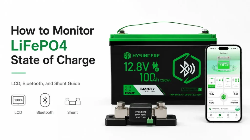
After replacing a lead-acid battery with LiFePO4, the original battery gauge may remain near “full” for a long time and then drop rapidly. A battery-mounted LCD, Bluetooth app, inverter and external shunt may also report different state-of-charge values for the same system.
This does not necessarily mean that the battery is faulty.
Many basic lead-acid gauges estimate remaining capacity from terminal voltage or use parameters calibrated for flooded, AGM or gel batteries. LiFePO4 has a relatively flat discharge-voltage curve through much of its usable capacity. As a result, voltage alone provides limited resolution for estimating LiFePO4 state of charge in the middle of the discharge cycle.
Before choosing a monitoring method, determine whether the project needs to monitor an individual battery or the complete battery bank and electrical system—not only whether a screen or phone connection is available.
What Is LiFePO4 State of Charge?
State of charge, or SOC, is an estimate of how much usable charge remains in a battery relative to its available capacity.
SOC is not a directly measured value like temperature. A battery management or monitoring system may estimate it using a combination of:
- Battery voltage;
- Current flowing into and out of the battery;
- Accumulated amp-hours;
- Temperature;
- Configured battery capacity;
- Charge-completion conditions;
- Calibration and synchronisation history.
SOC is also different from:
- Terminal voltage;
- Nominal battery capacity;
- State of health, or SOH;
- Estimated operating time remaining;
- BMS protection status.
For example, two batteries can show similar terminal voltages while having different SOC values because of differences in load, temperature, rest time, usable capacity, ageing and calculation method.
Why Does a Lead-Acid Battery Gauge Misread LiFePO4?
1. The gauge uses a lead-acid voltage profile
Lead-acid battery voltage normally changes more visibly as the battery discharges. This allows some basic gauges to use voltage as an approximate indication of remaining capacity.
LiFePO4 has a relatively flat discharge-voltage curve through much of its normal operating range. The remaining charge can change considerably while the voltage changes only slightly.
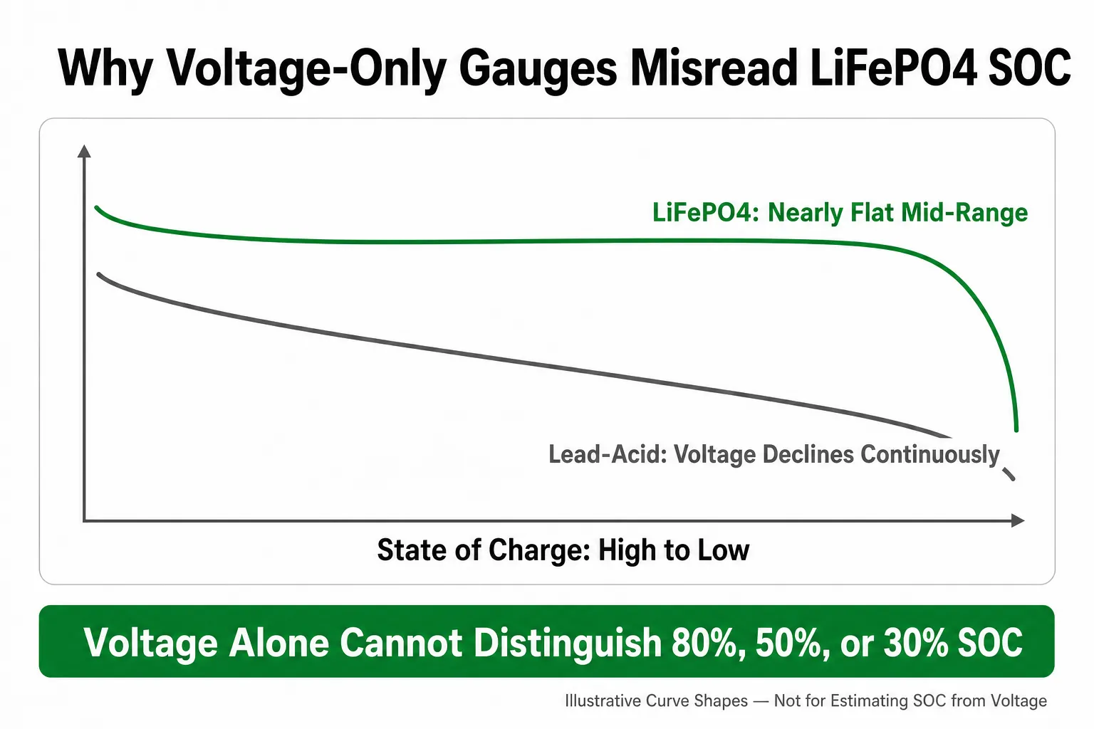
When an old gauge continues to use a lead-acid voltage profile, it may:
- Remain near full after energy has already been consumed;
- Show uneven percentage changes;
- Drop rapidly near the end of discharge;
- Provide insufficient warning before the battery stops supplying power.
2. Charging and load voltage are not the same as rested voltage
A solar controller, alternator or battery charger can raise terminal voltage while charging. An inverter, motor, pump or other high-current load can temporarily reduce it.
A high voltage while charging does not by itself confirm that the battery is full. A voltage drop under load does not by itself prove that the battery is nearly empty.
3. Voltage changes more rapidly near the ends of the curve
LiFePO4 voltage is relatively stable through the middle of the discharge cycle, but it changes more noticeably near full charge and near the lower end of the usable range.
A voltage-based gauge can therefore appear stable for a long time and then fall quickly.
4. Different devices measure different parts of the system
A battery BMS, Bluetooth app, inverter and external shunt can use different data sources and measurement boundaries. Their capacity settings, synchronisation conditions and calculation algorithms may also differ.
Different SOC readings do not automatically mean that one device is defective. The first step is to identify what each device is measuring.
Voltage Gauge vs. LCD vs. Bluetooth vs. Shunt
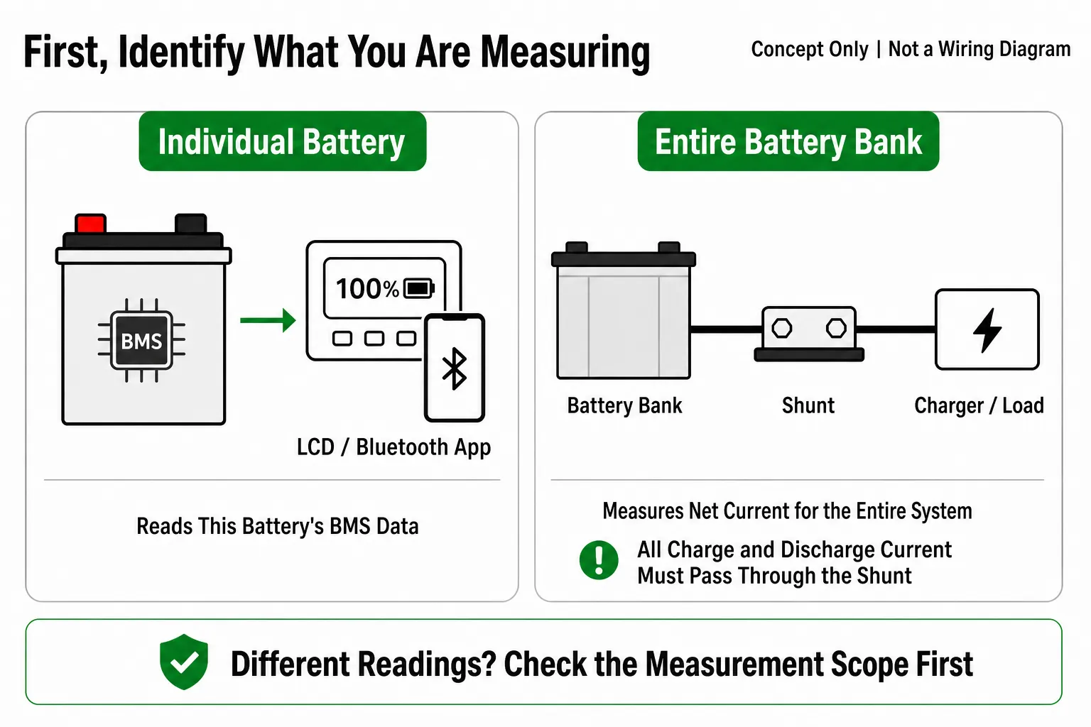
Monitoring methods should be compared by both their user interface and their measurement scope. The concept diagram below separates an individual-battery reading from a whole-bank measurement.
| Monitoring method | Data source | Main advantage | Main limitation | Typical use |
|---|---|---|---|---|
| Existing lead-acid gauge or voltmeter | Terminal voltage | Low cost and useful for basic voltage checks | Voltage alone provides limited LiFePO4 SOC resolution | Simple equipment requiring only a basic voltage indication |
| Battery-mounted LCD | Internal BMS or sensor data | Immediate local access without a phone | Available parameters and the SOC algorithm depend on the model | Individual batteries, maintenance and local inspection |
| Bluetooth app | Battery BMS data transmitted through the Bluetooth module | Convenient nearby access through a phone | Range, history and displayed parameters are model-specific | RV, marine, solar and individual smart batteries |
| External shunt | Current entering and leaving the complete battery bank | Measures net charge and discharge current for the complete bank at a defined system boundary | Requires correct wiring, capacity settings, full-charge criteria and synchronisation | Multi-battery banks, inverters, solar and complete DC systems |
| CAN or RS485 system monitoring | Communication between the BMS and host controller | Supports equipment integration and central management | Protocol, registers and master/slave configuration must match | OEM equipment, energy storage systems and industrial projects |
LCD and Bluetooth are primarily data-access interfaces. They do not, by themselves, determine SOC accuracy.
Accuracy depends on the measurement source, estimation algorithm, configured capacity, calibration state and system installation.
A shunt-based monitor is not automatically accurate simply because it has been installed. All charge and discharge current must pass through the shunt, and the monitor must be configured with the actual battery-bank capacity, full-charge criteria and synchronisation parameters.
When Should You Choose an LCD Battery?
An LCD battery is useful when operators need to check battery information directly at the installation, for example when:
- Maintenance personnel need an immediate local reading;
- The battery is installed where the screen remains visible;
- The project should not depend on a phone or wireless connection;
- An individual battery requires simple on-site status monitoring.
The Hysincere LF1250N-SL 12.8V 50Ah Smart LCD LiFePO4 battery provides 640Wh of rated energy, a battery-mounted smart LCD and IP65 protection for projects requiring local battery-status access.
The exact parameters available on the screen should be confirmed against the final product specification and display configuration.
When Should You Choose Bluetooth Monitoring?
Bluetooth is suitable when users want nearby access through a phone without installing a separate wired display. Typical applications include:
- RV and camper house batteries;
- Marine auxiliary-power systems;
- Solar and off-grid power;
- Batteries installed inside a compartment or enclosure.
The Hysincere LF12100N-B 12.8V 100Ah Bluetooth LiFePO4 battery provides 1280Wh of rated energy, Bluetooth communication and IP67 protection for RV, marine, solar and outdoor power projects.
Bluetooth communication should not automatically be described as cloud-based remote monitoring. Displayed parameters, connection range, history, alarms and software functions depend on the selected battery model, BMS and app version.
For a broader comparison of standard, LCD, Bluetooth and self-heating configurations, see the LiFePO4 lead-acid replacement feature guide.
When Is an External Shunt Appropriate?
In a bank made up of multiple batteries, or in a solar, inverter, RV or marine electrical system, the operator may need to monitor net current and accumulated charge for the complete bank rather than inspect one battery.
An external shunt or system-level battery monitor can then be evaluated.
A shunt is normally installed in the battery bank’s main system-negative path to measure current entering and leaving the bank. The connected battery monitor uses those measurements to estimate remaining capacity. Reliable SOC readings depend on correct wiring, voltage and current measurements, battery settings and synchronisation according to the monitor’s instructions.
A shunt is particularly useful when:
- Several batteries form one battery bank;
- Solar, chargers, inverters and DC loads share the same bank;
- The project needs to measure net charge and discharge current for the complete bank;
- A unified bank-level SOC or remaining operating-time estimate is required;
- Individual Bluetooth connections are inconvenient to manage.
This article discusses external shunts as a system-monitoring method; it does not imply that Hysincere currently sells them as standalone products.
Why Do the Bluetooth App, LCD and Shunt Show Different SOC Values?
Common causes include:
1. They measure at different locations
An LCD or Bluetooth app may display data from one battery’s BMS. A shunt measures current at the battery-bank boundary, while an inverter may use its own voltage-based estimate.
They are not necessarily measuring the same part or scope of the system.
2. The configured capacities are different
If a monitor is configured for 100Ah but the actual bank is 200Ah, its SOC calculation will be incorrect. Effective battery capacity can also change as a battery ages.
3. The monitor has not synchronised
Current-counting systems accumulate small measurement errors. If the system does not regularly meet the correct full-charge detection conditions, the estimated SOC can drift.
4. Some current does not pass through the shunt
If the negative connection from a charger, load or chassis ground does not pass through the shunt, the monitor cannot record that current and the SOC estimate will gradually diverge.
5. Voltage is affected by load, charging and temperature
Devices may sample at different times or under different loads. This can create different voltage and SOC estimates even when no component has failed.
6. Individual batteries behave differently within a bank
Current may not divide perfectly between parallel batteries. The BMS data from one battery does not necessarily represent the complete bank.
How to Troubleshoot an Inaccurate LiFePO4 SOC Reading
Use this six-step sequence:
- Identify which device produces each SOC value and whether it monitors an individual battery or the complete battery bank.
- Confirm that the existing gauge or monitor supports LiFePO4 rather than only flooded, AGM or gel lead-acid profiles, and that it is not using a lead-acid voltage curve.
- Verify the battery type, system voltage, configured bank capacity, series/parallel arrangement and full-charge detection criteria.
- Check monitor alarms and wiring. If an alarm is present, stop charging and discharging and identify the cause. Before inspecting wiring, isolate chargers and loads and follow the equipment manual. With a shunt, confirm that every charger, load and chassis-ground negative connection is on the system side of the shunt so that all charge and discharge current passes through it. If the battery stops supplying power, also inspect BMS protection events, current demand, terminals, cable voltage drop and low-voltage settings.
- Charge the battery using the method specified for the final battery model. After the required full-charge conditions are met, follow the monitor manufacturer’s instructions for automatic or manual SOC synchronisation.
- Retest and compare readings at the same time and under the same load and temperature conditions.
If the reading is still inaccurate: Record the readings and alarm information, then contact technical support. Do not bypass, disable or alter BMS protection to force the battery to continue operating.
A multimeter is useful for verifying terminal voltage and basic wiring, but one real-time voltage measurement should not be treated as an exact LiFePO4 SOC reading.
How Should a Lead-Acid-to-LiFePO4 Project Plan Battery Monitoring?
Battery monitoring should be selected after reviewing the complete electrical system. Use the 10-point lead-acid-to-LiFePO4 compatibility checklist to verify voltage, charger profile, BMS current, wiring, temperature, installation and series/parallel configuration.
As a practical guide:
- Individual battery with on-site inspection: evaluate a battery-mounted LCD;
- Individual smart battery with phone access: evaluate Bluetooth;
- An RV, marine or solar system with a multi-battery bank: evaluate a shunt-based battery monitor;
- OEM or industrial equipment: define CAN, RS485, display and host-controller requirements;
- Simple equipment without frequent monitoring needs: a standard battery may be sufficient.
RV projects should also account for solar charging, inverters and house loads described in the Hysincere RV battery application. Marine projects should consider electronics, pumps, navigation loads and battery-compartment conditions covered by the marine battery application.
What Monitoring Information Should a Buyer Provide?
For an accurate recommendation on an LCD, Bluetooth, shunt or communications solution, provide:
- Brands, model numbers and photographs of the original battery and gauge;
- System voltage, capacity and number of batteries;
- Series or parallel configuration;
- Charger, solar controller, alternator and inverter models;
- Maximum continuous and peak current;
- Whether local display or phone access is required;
- Whether the project needs individual-battery or complete-bank SOC;
- CAN, RS485 or other communication requirements;
- Data-history, alarm or remote-monitoring platform requirements;
- Project quantity, destination market and certification requirements.
Hysincere can evaluate voltage, capacity, BMS current ratings, display method, communication protocol, terminals, enclosure and wiring for project-specific requirements. Submit the existing system information through the custom lithium battery solutions page.
Conclusion
LiFePO4 remaining capacity should not be estimated solely from an old lead-acid gauge or one terminal-voltage reading.
An LCD provides convenient local access, Bluetooth provides nearby access to an individual smart battery, and a correctly installed and configured shunt-based battery monitor can measure whole-bank current and estimate whole-bank SOC. OEM and industrial systems may also require CAN, RS485 or host-controller integration.
The right solution is not the monitor with the longest feature list. It is the monitoring method that matches the battery, measurement boundary, electrical system and project data requirements.
Choose the Right LiFePO4 Monitoring Setup for Your Project
Share your battery bank, charger, inverter, load, monitoring and communication requirements. Hysincere can evaluate battery configuration, BMS, LCD, Bluetooth, CAN/RS485 and project-specific integration.
LiFePO4 SOC Monitoring FAQ
Can I continue using the original lead-acid battery gauge?
It may remain useful for basic voltage indication or simple alarms if its voltage range is compatible. For a more dependable LiFePO4 SOC estimate, use a monitor with suitable LiFePO4 settings, BMS data or an appropriately configured shunt.
Is Bluetooth more accurate than an LCD?
Not automatically. Bluetooth and LCD are different interfaces. Accuracy depends on the measurement source, SOC algorithm, battery-capacity setting, calibration and battery design.
Does one Bluetooth battery still need a shunt?
Not necessarily. Bluetooth may be sufficient for nearby access to an individual battery. A shunt becomes more relevant when the project needs to measure a complete battery bank and all connected charging and load currents.
Why does the battery app disagree with the inverter?
They may use different measurement points, capacity settings and algorithms. The inverter may use a voltage-based estimate while the battery app reads BMS data.
Why does the gauge remain high and then suddenly fall?
Common causes include the flat LiFePO4 voltage curve, a lead-acid-specific gauge profile, missing SOC synchronisation and voltage changes under load. Check the monitor settings, charge condition, connected load and BMS records together.
This article is for system selection and troubleshooting guidance. SOC accuracy depends on the specific battery, BMS, monitor, installation and calibration. Follow the final battery and monitoring-device documentation for commissioning and protection settings.